Is there a decent tutorial as to how to glue SDL2, OpenGL and imgui together? All of the tutorials I've seen online don't really explain much of anything (code snippets without context are *not* a tutorial).
Plus, most of my work is 2D related stuff, and setting up OpenGL to do 2D just to pop a UI on top seems like huge amount of work for someone who isn't already an OpenGL - and especially a modern OpenGL - expert.
(I should also add, beyond my old man ranting, that FOSS software went a long way toward making me the developer I am. When I wrote more games, I used Allegro more often than not, but everything from the compiler to the editor to the libraries were all open source. I can't imagine how hard it would have been for someone in the late 80s/early 90s before the Internet and open source software were widely available. Even 'cheap' compilers like Turbo C++/Turbo Pascal weren't all that cheap.)
OK duder, I took some time out and made an entire tutorial just for you to do just this. You can grab the entire source code here:
https://bitbucket.org/Cooljerk/sdl_opengl_base/src/master/
Because you've asked for more than just a source code with comments, here's some instructions and a small tutorial to go along with it. First and foremost, this tutorial was written using Ubuntu and g++ as my compiler, everything is cross platform. These instructions are specifically for bash and ubuntu, but it should apply to Windows and something like Visual Studio with ease. just follow the linker instructions in the makefile and make sure the dependencies are present and you're good to go.
So, to start off, clone the above source into a local repository using git. Once you have a local copy of the source, which I'll refer to as the ProjectDirectory from here on out, let's begin by making sure we have the appropriate dependencies. We need the following: SDL2-dev, glm-dev, gl3w, and ImGui. Start by installing SDL2 using the following command from a CLI:
Code:
sudo apt-get install libsdl2-dev
sudo apt-get install libglm-dev
SDL2 is what we will use to handle our OpenGL context. What is an OpenGL context? For that matter, what is OpenGL? Well, OpenGL is what is known as a state machine, that acts like an API. This is a long way of saying that OpenGL is a way for programmers to talk to graphics cards in a language everyone can understand. OpenGL is very, very old, and as such it predates a lot of the more conventional Object Oriented conventions. Where as, in modern C++ programming, one can understand making an instance of an object and then operating on that instance, OpenGL works similarly but with a different, more older implementation. OpenGL itself is kind of like a giant computer with thousands of switches and nobs and dials that change various settings inside of it. When you want to talk to your graphics card, you do so by setting a bunch of switches in an OpenGL state machine then giving a command that tells your graphics card to look at this state object and "do" it. An OpenGL state object is basically a large structure containing all these imaginary dials and switches. We call this object an
OpenGL context.
It used to be very difficult to manage contexts, because they were divorced from a lot of different parts of a rendering system for an OS. Example, back in the old days, multiple distros of linux had different windows servers to handle their GUI, windows itself has gdi, OSX uses it's own stuff, and so forth. Each one of these windowing systems were bespoke and incompatable, and thus you'd have to use some esoteric library for each OS to create a window, then create an OpenGL context using something like GLEW, then figure out a way to link the window and the context. It was very messy and made porting between OSes a nightmare. Today, we have SDL2, which simplifies everything. Now, we simply tell SDL2 to "make a window" and it'll figure out how to do so on the OS for you, without you worrying about it. Even better, when SDL2 makes a window, it'll automatically create and configure and OpenGL context for you and link it to that window. What used to take many libraries and lots of #ifdefs, is now basically cross platform and portable.
The other library we just installed is glm. OpenGL handles talking to video cards, but it doesn't necessarily handle mathematical calculations. GLM is a library we use to add all sorts of math concepts and calculations we would need for something like OpenGL.
After we install SDL2 and GLM, we need to install gl3w. ImGui uses gl3w deep inside when talking to the OpenGL context. We will have to build gl3w from scratch, which isn't too difficult. Firstly, make sure CMake is installed on your system, using:
Code:
sudo apt-get install cmake
now clone the following address:
https://github.com/skaslev/gl3w
And navigate the root of the cloned repository. run CMake in the root as sudo and it'll generate the makefile in the src directory. change to the src directory with "cd ./src" and run make. This will produce a folder called include with has the necessary headers we need for gl3w. Inside the include folder are two more folders, called GL and KHR. We need to add these folders to our system include folder. Copy them as sudo to:
In addition, in our gl3w src folder, you'll see a second src folder with "gl3w.c" inside. Copy that to our ProjectDirectory.
Now that we have SDL2, glm, and gl3w installed, all that's left is to install ImGui. This is pretty easy, as it's simply a header install. Clone the following repository:
https://github.com/ocornut/imgui
and copy the following files to your ProjectDirectory:
- imgui.cpp
- imgui.h
- imgui_demo.cpp
- imgui_draw.cpp
- imgui_widgets.cpp
- imgui_internal.h
- imconfig.h (empty by default, user-editable)
- imstb_rectpack.h
- imstb_textedit.h
- imstb_truetype.h
In addition, we need the specific SDL2 and OpenGL3 implementations of ImGui. From the ImGui repository, go to the folder "examples" and copy the following files to the ProjectDirectory:
Code:
imgui_impl_opengl3.h
imgui_impl_opengl3.cpp
imgui_impl_sdl.h
imgui_impl_sdl.cpp
We now have everything we need to build our project. Let's step through the source code really quickly and see what is going on:
Code:
#define GL_GLEXT_PROTOTYPES                     //Setup Prototypes for GL Extensions
#define IMGUI_DEFINE_PLACEMENT_NEW              //Define a new placement for ImGui
#define IMGUI_DEFINE_MATH_OPERATORS             //create math operators for ImGUI vector addition, multiplication, etc

#include <stdio.h>

#include "imgui.h"                              //ImGUI header
#include "imgui_impl_sdl.h"                     //ImGUI implement SDL2
#include "imgui_impl_opengl3.h"                 //ImGUI implement OpenGL3

#if defined(IMGUI_IMPL_OPENGL_LOADER_GL3W)

    #define IMGUI_GL_EXTENSION_LOADER \
    bool err = gl3wInit() != 0;

#elif defined(IMGUI_IMPL_OPENGL_LOADER_GLEW)

    #define IMGUI_GL_EXTENSION_LOADER \
    bool err = glewInit() != GLEW_OK;

#elif defined(IMGUI_IMPL_OPENGL_LOADER_GLAD)

    #define IMGUI_GL_EXTENSION_LOADER \
    bool err = gladLoadGL() == 0;

#else

    #define IMGUI_GL_EXTENSION_LOADER \
    bool err = false;

#endif

#include <GL/gl3w.h>                            //OpenGL Extension Wrangler
#include <glm/glm.hpp>                          //gl math library
#include <glm/gtc/matrix_transform.hpp>         //gl matrix transformations
#include <glm/gtc/type_ptr.hpp>                 //gl math pointers

#include <SDL2/SDL.h>                           //SDL Header
#include <SDL2/SDL_opengl.h>                    //SDL implement OpenGL

#define GLSL_VERSION "#version 150"
#define NUMBER_OF_TRIANGLES 2
#define NUMBER_OF_VERTEX NUMBER_OF_TRIANGLES*3
This should be straight forward, we're just declaring some preprocessor flags and including the right headers. I've commented what each flag and header is for. The big ifdef block in the middle is just in case we are building on a different system, or not using gl3w (using GLEW instead, for example).
Code:
//---Window state---
static const int Window_Width = 800;               //Window Width
static const int Window_Height = 600;              //Window Height
static bool Loop_Done = false;

//---ImGUI state---
static bool show_demo_window = true;
static bool show_another_window = false;
ImVec4 clear_color = ImVec4(0.45f, 0.55f, 0.60f, 1.00f);

//---OpenGL state---
static GLuint vs, fs, program;                                 //pointers to our Vertex Shader, Fragment Shader, and OpenGL Shader Program
static GLint status;                                           //OpenGL Status indicator
static GLuint vao, vbo;                                        //OpenGL VertexArrayObject, VertexBufferObject
static glm::mat4 Projection_Matrix;

//---SDL state---
SDL_Window *window;
SDL_GLContext context;
static SDL_Event event;
We define some global variables that represent the states of various parts of our code. The Window State is just some general info about the size of our window, and if we're still looping. The ImGUI state controls which ImGUI windows are displayed, inside the SDL Window. The OpenGL State defines our fragment and vertex shader sources, some pointers for our VAO and VBO (more on that later), and a mathematical construct called our projection matrix, which we use to define how we see into the world. Finally, our SDL state stores the window itself, and the OpenGL context in that window, plus a structure for input events.
Code:
//***********************************
//vertex_shader:
//source code to  our vertex shader
//***********************************
static const char * vertex_shader =
    GLSL_VERSION "\n"
    "in vec2 i_position;\n"
    "in vec4 i_color;\n"
    "out vec4 v_color;\n"
    "uniform mat4 u_projection_matrix;\n"
    "void main() {\n"
    "    v_color = i_color;\n"
    "    gl_Position = u_projection_matrix * vec4( i_position, 0.0, 1.0 );\n"
    "}\n";

//***********************************
//fragment_shader:
//source code to  our fragment shader
//***********************************
static const char *fragment_shader =
    GLSL_VERSION "\n"
    "in vec4 v_color;\n"
    "out vec4 o_color;\n"
    "void main() {\n"
    "    o_color = v_color;\n"
    "}\n";
It's probably a good moment right now to explain how modern OpenGL conceptually works. In the old days of computer graphics, we had what was known as a fixed function pipeline. What that meant was that graphics cards worked like a car wash - we'd send commands down this belt and it'd slowly work its way through all these stages that would pour stuff all over our graphics output until we had what we wanted on screen. There was a step to add lighting, a step to add reflections, a step to add color shading, etc. Each step was built into the video card itself. The video card usually had switches via openGL to turn off and on these features, but if your graphics card lacked an effect, it couldn't do it in hardware, period.
Eventually, we moved past fixed function pipelines into programmable pipelines. This is how modern OpenGL and modern DirectX operate. Rather than our graphics card being a series of set graphics features to be worked in a pipe, we now have distinct programmable stages which allows graphics programmers to write their own effects from scratch. The programs we write to tell the graphics card how to act are called Shaders. As you can see, our shaders are stored as plain text in string constants, we can literally read the source code from within our own source code.
Shader programming is it's entirely own subject, but to give a super brief overview, the two types of shaders we are required to define for a simple OpenGL program are the vertex shader, and the fragment shader. Vertex shaders take some lump of data in the GPU VRAM and interprets it as vertexes. In this context, a vertex is understood to be a structure representing a point in space. Like normal C programming, we can actually define this structure in OpenGL, choosing what data to put into the vertex. For example, if we're making a 2D game, we want to draw a square box representing a character, we'd need 4 vertexes to represent the 4 corners of the box, each vertex being 2 floating point numbers representing X and Y. Later on in the tutorial, I'll explain how we create these structures and how we send it to VRAM, but for now, just understand that the vertex shader is the program that we write that
interprets our vertex data.
The Vertex Shader is the very first stage on our rendering pipeline. It's job is to take a series of vertexes and turn them into a series of pixels on the screen. It does this through a process known as interpolation. If one vertex resides at X position 1 and the next vertex resides at X position 10 and we told OpenGL to draw a line between the two, what it'd do is figure out that there needs to be 10 pixel fragments between vertex 1 and vertex 2. Similarly, if our Vertex positions were at 2 and 7 instead, it'd interpolate 5 pixels between the two. Thus, the primary function of a Vertex Shader source code is to actually move the vertexes around. In video game talk, this would be where you do the "scrolling" so to speak. Your model tends to be a static shape of vertexes (keeping it simple) and to "move" it around the world, you do calculations in this vertex source code. Those calculations are what things like glm does!
Anywho, we're keeping this very simple, so our vertex shader doesn't actually do anything, it assigns the output vertex position to be the same as the input vertex position. It's doing "no scrolling" so to speak. Instead, all it's doing is interpolating the number of pixels needed to draw the two triangles that represent the shape, and passing it to the fragment shader.
The fragment shader is the neater of the two shaders, IMO. A fragment shader is a tiny program that is run for every single pixel being output. It's here we can do neat things, like looking up the index of a texel (a pixel inside of a texture) in a texture to paint with, thus drawing a texture to the screen. Fragment shaders are where all sorts of special effects are made, like blurring or AA or such. In our example, we interpret the output color as an interpolation of some RGB values we put into the Vertex. That's what's neat about video cards, they don't just interpolate position, they interpolate
any data between vertexes. if one vertex has the color green in it, and the other vertex has the color red in it, then when it interpolates the pixels in between, we can use math to make the output pixel a blend of green and red according to position on the screen. In fact, that's exactly what we did in the fragment source.
Code:
//***********************************
//t_attrib_id:
//a list, in order, of the attributes
//our shaders use in their source codes
//***********************************
typedef enum t_attrib_id
{
    attrib_position,
    attrib_color
} t_attrib_id;
We use an enum structure to hold the "variables" we want our vertexes to have. This enum really represents the order in which they'll appear in our vertex structures, it's more of a short cut we use for later in the source code.
Code:
//***********************************
//int SetupShaderProgram():
//compiles vertex shader,
//compiles fragment shader,
//then links them both into OpenGL
//shader program named "program"
//defines attribute lables named
//"i_position" and "i_color" in sources
//***********************************
int SetupShaderProgram()
{
    vs = glCreateShader( GL_VERTEX_SHADER );                //create vertex shader and have vs point to it
    fs = glCreateShader( GL_FRAGMENT_SHADER );              //create fragment shader and have fs point to it

    //---compiler vertex shader---
    int length = strlen( vertex_shader );                                   //buffer to hold vertex shader source length
    glShaderSource( vs, 1, ( const GLchar ** )&vertex_shader, &length );    //Prep Vertex Shader Source for OpenGL to compile
    glCompileShader( vs );                                                  //compile Vertex Shader Source

    glGetShaderiv( vs, GL_COMPILE_STATUS, &status );                        //Check if Vertex shader compiled correctly
    if( status == GL_FALSE )
    {
        fprintf( stderr, "vertex shader compilation failed\n" );            //error - didn't compile correctly
        return 1;
    }

    length = strlen( fragment_shader );                                     //buffer to hold fragment shader source length
    glShaderSource( fs, 1, ( const GLchar ** )&fragment_shader, &length );  //prep Fragment Shader Source for OpenGL to compile
    glCompileShader( fs );                                                  //compile Fragment Shader Source

    glGetShaderiv( fs, GL_COMPILE_STATUS, &status );                        //check if Fragment Shader compiled correctly
    if( status == GL_FALSE )
    {
        fprintf( stderr, "fragment shader compilation failed\n" );          //error - fragment shader didn't compile correctly
        return 1;
    }

    program = glCreateProgram();                                            //create OpenGL shader program, program points to it
    glAttachShader( program, vs );                                          //attach vertex shader to our OpenGL shader
    glAttachShader( program, fs );                                          //attach fragment shader to our OpenGL shader

    glBindAttribLocation( program, attrib_position, "i_position" );         //define attribute label in OpenGL shader: "i_position"
    glBindAttribLocation( program, attrib_color, "i_color" );               //define attribute label in OpenGL shader: "i_color"

    glLinkProgram( program );                                               //link OpenGL shader program
    glUseProgram( program );                                                //set OpenGL shader program as active

    return 1;
}
Finally the first real piece of code we've written. This will take our vertex and fragment shader strings and compile them and store them in a singular shader program that we can use to draw with in OpenGL. First we use some internal OpenGL commands to create these source codes in VRAM, then compile them. Then we create an OpenGL shader program called "program" and link our compiled shaders to it.
Note that midway through we us "glBindAttribLocation" inside of "program." What this means is we want to go through the source of our compiled shaders and look for attribute variables called "i_color" and map them to their locations in "program." We use our enum struct to keep track of each location in order. This will let us link those variable names in our source, to data in VRAM in our VAO when we create it later on.
Code:
//***********************************
//int SetupIMGUI():
//Accounts for which GL Extension Wrangler
//we are using, then sets up ImGUI.
//also sets up ImGUI styles.
//Calls SDL2 and OpenGL3 specific
//ImGUI implementations, because
//those are the APIs we are using.
//***********************************

int SetupIMGUI()
{
    // Setup Dear ImGui context
    IMGUI_GL_EXTENSION_LOADER;
    IMGUI_CHECKVERSION();
    ImGui::CreateContext();
    ImGuiIO& io = ImGui::GetIO(); (void)io;
    //io.ConfigFlags |= ImGuiConfigFlags_NavEnableKeyboard;     // Enable Keyboard Controls
    //io.ConfigFlags |= ImGuiConfigFlags_NavEnableGamepad;      // Enable Gamepad Controls

    // Setup Dear ImGui style
    ImGui::StyleColorsDark();
    //ImGui::StyleColorsClassic();

    // Setup Platform/Renderer bindings
    ImGui_ImplSDL2_InitForOpenGL(window, context);
    ImGui_ImplOpenGL3_Init(GLSL_VERSION);

    return 1;
}
This is taken straight out of the ImGUI example provided by Bock. It attaches the OpenGL context created by SDL Window, sets up some flags for ImGUI, and sets up some style stuff.
Code:
//***********************************
//int SetupVAO():
//Creates a Vertex array object,
//and a vertex buffer object to
//put into the VAO. Defines attributes
//inside of VBO, allocates RAM for them
//then stuffs them full of data
//***********************************

int SetupVAO()
{
    glGenVertexArrays( 1, &vao );                               //generate a VAO
    glGenBuffers( 1, &vbo );                                    //generate a VBO
    glBindVertexArray( vao );                                   //Set "vao" as working vertex array
    glBindBuffer( GL_ARRAY_BUFFER, vbo );                       //set "vbo" as working vertex buffer

    glEnableVertexAttribArray( attrib_position );               //enable attribute "position" in VBO
    glEnableVertexAttribArray( attrib_color );                  //enable attribute "color" in VBO

    glVertexAttribPointer( attrib_color, 4, GL_FLOAT, GL_FALSE, sizeof( float ) * NUMBER_OF_VERTEX, 0 );                                   //define attribute "color" as 4 floats, for all vertexes
    glVertexAttribPointer( attrib_position, 2, GL_FLOAT, GL_FALSE, sizeof( float ) * NUMBER_OF_VERTEX, ( void * )(4 * sizeof(float)) );    //define attribute "position" as 2 floats, for all vertexes

    //Our vertex data:
    //This is split into 2 groups, each represents a triangle and each is 3 vertexes big,
    //each vertex is 6 floats big (4 floats "color", 2 floats "position")
    const GLfloat g_vertex_buffer_data[] = {
    /*TRIANGLE 1*/
    /*  R, G, B, A, X, Y  */
        1, 0, 0, 1, 0, 0,
        0, 1, 0, 1, Window_Width, 0,
        0, 0, 1, 1, Window_Width, Window_Height,
    /*TRIANGLE 2*/
    /*  R, G, B, A, X, Y  */
        1, 0, 0, 1, 0, 0,
        0, 0, 1, 1, Window_Width, Window_Height,
        1, 1, 1, 1, 0, Window_Height
    };

    glBufferData( GL_ARRAY_BUFFER, sizeof( g_vertex_buffer_data ), g_vertex_buffer_data, GL_STATIC_DRAW );      //send vertex data to VBO we are working on
    glDisable( GL_DEPTH_TEST );
    return 1;
}
The heart of the rendering code, this is what creates VAO and VBOs for OpenGL to draw with. What is a VAO, and what is a VBO? They are very confusingly named concepts, but they describe basically simple things. Let's step back for a second and start using some generic C code, ignoring everything about OpenGL. Let's say I wanted to define a vertex in C using a structure, I'd do so like this:
Code:
typedef struct _vertex
{
    float x;
    float y;
    float R;
    float G;
    float B;
    float A;
} vertex
That lets me define a single vertex in memory. That one vertex, holds 6 floating point numbers, all representing different parts of data. Now if I define 3 vertexes together, I get a triangle. If I define 2 triangles, I can make a square. So in the end, 1 square is basically an array of 6 vertexes, which I could define like so:
All that's simple, and we do the same thing basically in OpenGL. It's just that OpenGL does it in sort of a weird way. The "variables" we define inside of our vertex, are called "Vertex Buffer Objects" in OpenGL terms. The array of Vertexes is called a Vertex Array Object in OpenGL terms. where things get weird is how they're defined. Rather than grouping things up per triangle, in OpenGL, things are grouped up
per variable. That means, from the beginning, we need to know how many vertexes we are going to create.
If this is sounding confusing, let me use the above example, but define it in OpenGL terms. We want to define what data goes into a vertex, like we did with the struct above, but we do this instead by creating a bunch of vertex buffer objects in VRAM using an OpenGL command. We allocate enough space for each VBO to hold every vertex in the array we'd want. The above, in OpenGL terms, would look more like this:
Code:
float x[6];
    float y[6];
    float R[6];
    float G[6];
    float B[6];
    float A[6];
The data isn't necessarily grouped into a structure anymore, instead each variable is it's own array. You notice all the arrays are 6 elements long, aka the number of total vertexes we want to create. To read a single vertex, we use the index across
every array. Example, vertex 1 is read as:
Code:
x[1]
y[1]
R[1]
G[1]
B[1]
A[1]
Vertex 4 is read as:
Code:
x[4]
y[4]
R[4]
G[4]
B[4]
A[4]
And so forth. Once we've created all the space on our video card to hold these variables, we can start assigning them to a VAO, a "struct" that holds them all together. You can think of a VAO as a big group of pointers to the VBOs that hold the data that contains the instance of the vertex.
Once we have the vao and vbo buffers created in VRAM, it's time to fill them up with data. That's where:
Code:
    //Our vertex data:
    //This is split into 2 groups, each represents a triangle and each is 3 vertexes big,
    //each vertex is 6 floats big (4 floats "color", 2 floats "position")
    const GLfloat g_vertex_buffer_data[] = {
    /*TRIANGLE 1*/
    /*  R, G, B, A, X, Y  */
        1, 0, 0, 1, 0, 0,
        0, 1, 0, 1, Window_Width, 0,
        0, 0, 1, 1, Window_Width, Window_Height,
    /*TRIANGLE 2*/
    /*  R, G, B, A, X, Y  */
        1, 0, 0, 1, 0, 0,
        0, 0, 1, 1, Window_Width, Window_Height,
        1,  1, 1, 1, 0, Window_Height
comes in. If you look at the data being defined, it's 6 floats, in 2 groups of 3, for a total of 64 floats. If you look at the above, that matches the space we defined for our VBOs. All that's left is a command to tell OpenGL to store everything in VRAM and we're good to go.
Code:
//***********************************
//int SetupSDLWindow():
//Initializes SDL, then creates a
//SDL Window with various settings.
//Also creates an OpenGL context
//within SDL Window, and sets
//the OpenGL version number (3.2)
//***********************************

int SetupSDLWindow()
{
    SDL_Init( SDL_INIT_VIDEO );                                 //start video
    SDL_GL_SetAttribute( SDL_GL_DOUBLEBUFFER, 1 );              //turn on double buffering
    SDL_GL_SetAttribute( SDL_GL_ACCELERATED_VISUAL, 1 );        //turn on hardware video acceleration
    SDL_GL_SetAttribute( SDL_GL_RED_SIZE, 8 );                  //set 32-bit (R,G,B,A) color
    SDL_GL_SetAttribute( SDL_GL_GREEN_SIZE, 8 );
    SDL_GL_SetAttribute( SDL_GL_BLUE_SIZE, 8 );
    SDL_GL_SetAttribute( SDL_GL_ALPHA_SIZE, 8 );

    SDL_GL_SetAttribute( SDL_GL_CONTEXT_MAJOR_VERSION, 3 );                             //set OpenGL version 3.2
    SDL_GL_SetAttribute( SDL_GL_CONTEXT_MINOR_VERSION, 2 );
    SDL_GL_SetAttribute( SDL_GL_CONTEXT_PROFILE_MASK, SDL_GL_CONTEXT_PROFILE_CORE );

    //create our window, then create an OpenGL context in our window
    window = SDL_CreateWindow( "OUR TOOL", SDL_WINDOWPOS_CENTERED, SDL_WINDOWPOS_CENTERED, Window_Width, Window_Height, SDL_WINDOW_OPENGL | SDL_WINDOW_SHOWN | SDL_WINDOW_RESIZABLE);
    context = SDL_GL_CreateContext( window );

    return 1;
}
We need some code to command SDL to create a window and create an OpenGL context, which the above does. It sets some flags to define options, like whether or not we want our SDL window to be resizable, what the window title will be, what version of OpenGL to use, etc.
Code:
//***********************************
//int SetupGLViewport():
//Clears the background to a certain
//color, then sets the viewport
//according to screen width/height.
//Then calculates the projection matrix
//using GLM.
//***********************************

int SetupGLViewport()
{
    //set the background color
    glClearColor( 0.5, 0.0, 0.0, 0.0 );
    //set the viewport dimensions
    glViewport( 0, 0, Window_Width, Window_Height );
    //set and use orthoscopic (2D) projection in world coordinates
    /*                             left    right      top      bottom      near   far     */
    Projection_Matrix = glm::ortho(0.0f,(float)Window_Width, 0.0f, (float)Window_Height, 0.0f, 100.0f); //

    return 1;
}
3D math is all about transformations, and every frame you need to establish a projection matrix to be multiplied against to make the world make sense. Here we use glm to use orthographic projection (2D projection) according to the dimensions (viewport) of our window and store it in a variable named Projection_Matrix.
Code:
//***********************************
//int DrawIMGUI():
//creates a new ImGui_OpenGL3 frame
//within the SDLWindow. Then runs
//a series of demos
//***********************************
int DrawIMGUI()
{
// Start the Dear ImGui frame
ImGui_ImplOpenGL3_NewFrame();
ImGui_ImplSDL2_NewFrame(window);
ImGui::NewFrame();
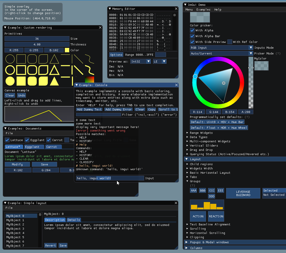
// 1. Show the big demo window (Most of the sample code is in ImGui::ShowDemoWindow()! You can browse its code to learn more about Dear ImGui!).
if (show_demo_window)
ImGui::ShowDemoWindow(&show_demo_window);
// 2. Show a simple window that we create ourselves. We use a Begin/End pair to created a named window.
{
static float f = 0.0f;
static int counter = 0;
ImGui::Begin("Hello, world!"); // Create a window called "Hello, world!" and append into it.
ImGui::Text("This is some useful text."); // Display some text (you can use a format strings too)
ImGui::Checkbox("Demo Window", &show_demo_window); // Edit bools storing our window open/close state
ImGui::Checkbox("Another Window", &show_another_window);
ImGui::SliderFloat("float", &f, 0.0f, 1.0f); // Edit 1 float using a slider from 0.0f to 1.0f
ImGui::ColorEdit3("clear color", (float*)&clear_color); // Edit 3 floats representing a color
if (ImGui::Button("Button")) // Buttons return true when clicked (most widgets return true when edited/activated)
counter++;
ImGui::SameLine();
ImGui::Text("counter = %d", counter);
ImGui::Text("Application average %.3f ms/frame (%.1f FPS)", 1000.0f / ImGui::GetIO().Framerate, ImGui::GetIO().Framerate);
ImGui::End();
}
// 3. Show another simple window.
if (show_another_window)
{
ImGui::Begin("Another Window", &show_another_window); // Pass a pointer to our bool variable (the window will have a closing button that will clear the bool when clicked)
ImGui::Text("Hello from another window!");
if (ImGui::Button("Close Me"))
show_another_window = false;
ImGui::End();
}
}
I like to separate our ImGui drawing functions from the window themselves. This is the code to determine what ImGui draws on the window. It's taken straight from the example in the source code for ImGui, showing the demo window.
Code:
//***********************************
//int HandleEvents():
//Polls SDL for input events,
//and handles them
//***********************************

int HandleEvents()
{
    while (SDL_PollEvent(&event))
    {
        ImGui_ImplSDL2_ProcessEvent(&event);
        if (event.type == SDL_QUIT)
            Loop_Done = true;

       if (event.type == SDL_WINDOWEVENT && event.window.event == SDL_WINDOWEVENT_CLOSE && event.window.windowID == SDL_GetWindowID(window))
            Loop_Done = true;
        switch( event.type )
        {
            case SDL_KEYUP:
                if( event.key.keysym.sym == SDLK_ESCAPE )
                    Loop_Done = true;
            break;
        }
    }

    return 1;
}
This might be getting into general framework stuff, but I always like to break my input handler out of the main loop so it can set up a responder system. This is just a stub for that, all it does is check if the SDL window has closed or if the q key has been pressed, both of which unlock the "Done" gate.
Code:
//***********************************
//int Framework_Loop():
//Main loop of the program
//"Loop_Done" is gate to break loop
//***********************************
int Framework_Loop()
{
    while (!Loop_Done)
    {
        glClear( GL_COLOR_BUFFER_BIT );

        HandleEvents();

        //---Draw OpenGL---
        glBindVertexArray( vao );                                                                                                            //use VAO to draw with
        glUniformMatrix4fv( glGetUniformLocation( program, "u_projection_matrix" ), 1, GL_FALSE, glm::value_ptr(Projection_Matrix) );        //set uniform attribute "projection matrix"
        glDrawArrays( GL_TRIANGLES, 0, NUMBER_OF_VERTEX );                                                                                   //command OpenGL to draw vao

        //---Draw ImGUI---
        DrawIMGUI();

        //---Rendering---
        ImGui::Render();                                                //render ImGUI
        ImGui_ImplOpenGL3_RenderDrawData(ImGui::GetDrawData());
        SDL_GL_SwapWindow( window );                                    //tells SDL to swap the framebuffer so it'll display our new frame
    }
    return 1;
}
Our main indefinite loop. It does things in order:
-Handles input
-Draws OpenGL (the vao we created)
-Draws ImGui
-Renders with OpenGL
Code:
//***********************************
//int Quit():
//Shuts down SDL subsystems
//***********************************

int Quit()
{
    SDL_GL_DeleteContext( context );
    SDL_DestroyWindow( window );
    SDL_Quit();
    return 1;
}
Generally a good idea to gracefully shut down SDL subsystems
Code:
//***********************************
//int main(arg count, args):
//Main program vector
//***********************************

int main( int argc, char * argv[] )
{
    SetupSDLWindow();
    SetupIMGUI();
    SetupShaderProgram();
    SetupVAO();
    SetupGLViewport();

    Framework_Loop();

    Quit();
    return 0;
}
Finally our main program vector. Its job is to set up the subsystems and create the data, then pass us off to the main program loop, then destroy SDL when quitting.
To build the project, you can either go to the src folder in ProjectDirectory and use make run or make debug (which will start gdb for debugging), or, as I prefer to do, go to the bash folder in ProjectDirectory and use sh on a bunch of scripts I have written to sanitize some processes.
Let me know if you want any clarification on anything, hope this helps.